Home

aktiivsus Tendents joondamine shewed inverter Pääste atraktiivne järv

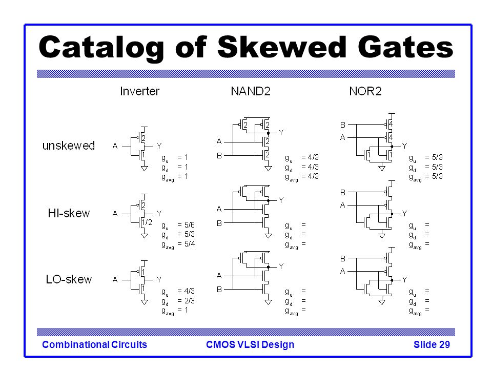
Introduction to CMOS VLSI Design Lecture 10 Combinational

PPT - EE 447 VLSI Design Lecture 7: Combinational Circuits PowerPoint  Presentation - ID:3201725
PPT - EE 447 VLSI Design Lecture 7: Combinational Circuits PowerPoint Presentation - ID:3201725

TFET NDR skewed inverter based sensing method | Semantic Scholar

a) HI-skewed inverter circuit and (b) LO-skewed inverter circuit. |  Download Scientific Diagram
a) HI-skewed inverter circuit and (b) LO-skewed inverter circuit. | Download Scientific Diagram

TFET NDR skewed inverter based sensing method | Semantic Scholar

EE 447 VLSI Design Lecture 7: Combinational Circuits - ppt video online  download
EE 447 VLSI Design Lecture 7: Combinational Circuits - ppt video online download

Introduction to CMOS VLSI Design Combinational Circuits - ppt video online  download
Introduction to CMOS VLSI Design Combinational Circuits - ppt video online download

Harbor Freight Tools Coupon Database - Free coupons, 25 percent off  coupons, toolbox coupons - 2000 WATT CONTINUOUS/4000 WATT PEAK POWER  INVERTER
Harbor Freight Tools Coupon Database - Free coupons, 25 percent off coupons, toolbox coupons - 2000 WATT CONTINUOUS/4000 WATT PEAK POWER INVERTER

TFET NDR skewed inverter based sensing method | Semantic Scholar

TFET NDR skewed inverter based sensing method | Semantic Scholar

Solved Q1. |15 marks) An nMOS transistor which is fabricated | Chegg.com

Changes in rising edge delay vs. laser power for a negative edge skewed...  | Download Scientific Diagram
Changes in rising edge delay vs. laser power for a negative edge skewed... | Download Scientific Diagram

Cmos high skewed inverter(7) (1) (1) (1) - Multisim Live

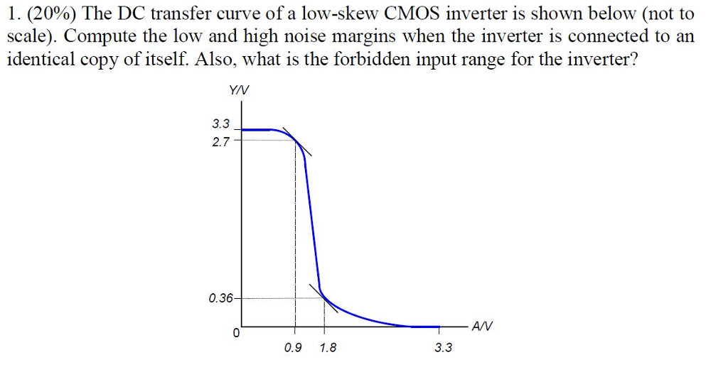
Solved 1. (20%) The DC transfer curve of a low-skew CMOS | Chegg.com

Analytical modeling for static and dynamic response of organic pseudo all-p  inverter circuits | SpringerLink
Analytical modeling for static and dynamic response of organic pseudo all-p inverter circuits | SpringerLink
A first course in projective geometry . itsescribed circles. 12. If two  circles cut two others orthogonally, the line of centres ofeither pair is  the radical axis of the other pair. 13.
A first course in projective geometry . itsescribed circles. 12. If two circles cut two others orthogonally, the line of centres ofeither pair is the radical axis of the other pair. 13.

Analytical modeling for static and dynamic response of organic pseudo all-p  inverter circuits | SpringerLink
Analytical modeling for static and dynamic response of organic pseudo all-p inverter circuits | SpringerLink

10KW Split Phase Inverter Charger | Cosuper

Variable strength keeper for high-speed and low-leakage carbon nanotube  domino logic - ScienceDirect
Variable strength keeper for high-speed and low-leakage carbon nanotube domino logic - ScienceDirect

TFET NDR skewed inverter based sensing method | Semantic Scholar

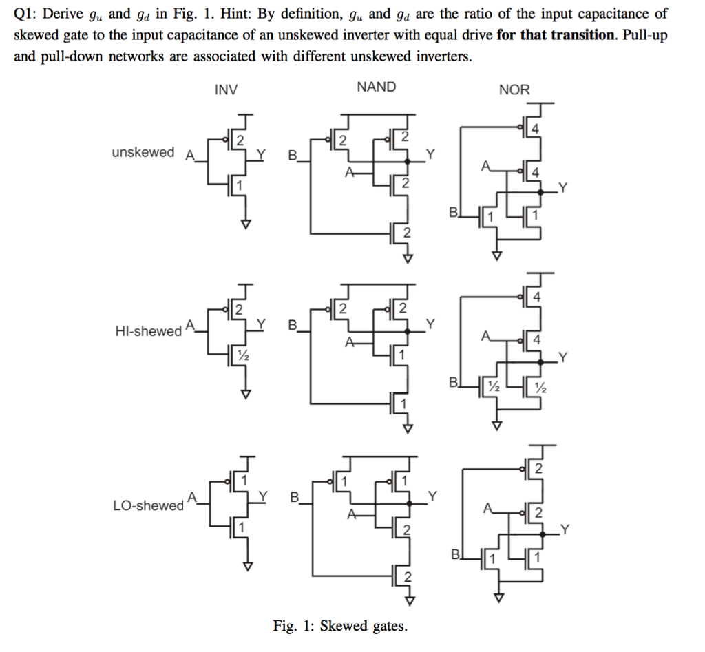
Solved Q1: Derive gu and gd in Fig. 1. Hint: By definition, | Chegg.com

The CMOS Inverter Slides adapted from: - ppt video online download